
Nylon MMF
 MarkForged Mechanical Features [MMF] is a series of blog posts detailing best practices for designing common traditional engineering parts and mechanical features for composite reinforced 3D printing with MarkForged printers.
Threaded components, holes and bolted connections are integral to a wide variety of engineering parts that you make and work with every day — so it only makes sense that at some point, you’re probably going to want to create 3D printed parts with threads too. Adding threaded surfaces to plastic 3D printed parts — even high strength, carbon fiber-reinforced parts from Markforged — requires more design work than simply modeling the threads in 3D or tapping an undersized hole. 3D printed plastics generally have much lower material yield strength than common prototyping metals, and the small feature dimensions of popular thread sizes (both metric and Imperial) mean that it’s fairly easy to overload and strip out 3D printed plastic threads. Since Markforged 3D printers print external walls of nylon around any internal composite fiber reinforcement, this limitation applies to us as well for common thread sizes. Not to worry! All is not lost — if the underlying plastic is too weak, you can replace it with metal! Here’s how to use metal threaded inserts to produce industrial strength threaded connections on your Mark Two 3D printer.
Threaded inserts that fit right in!
What you’ll need:
- 3D printed part with appropriate holes for threaded inserts
- Desired threaded inserts – heat-set or press-in
- Soldering iron
- (Optional) Threaded insert installation tip for soldering iron
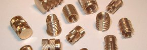
Markforged strongly recommends that you use metal threaded inserts when the need for strong threads arises in your design process. Threaded inserts are cylindrical metal tubes, commonly made of brass (although many different material options exist) with a pre-formed thread of the specified size running inside of the cylinder. The insert is embedded into a larger part and resists pull-out or torque-out due to a knurled, knobbed or threaded external surface designed to interface with and grip the bulk material of the part.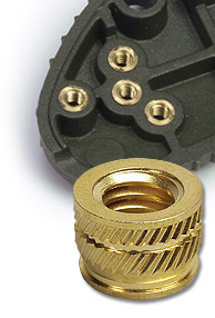 Threaded inserts are also much more wear resistant than threads made from the base plastic of your 3D printed part, and if you plan to be unscrewing and re-inserting a bolt or other threaded connection into your part frequently, an insert is the way to go.
Threaded brass inserts are easy to find through a variety of manufacturers, including McMaster-Carr, in both the press-in and heat-set varieties. We prefer the heat-set type, since melting and reflowing the surrounding nylon of a part guarantees the most intimate bond between the nylon and the threaded insert body. This in turn ensures a much stronger pull-out and torque-out rating of the resulting thread as compared to press-in inserts. Since Markforged printers build parts from thermoplastics, unlike stereolithographic (SLA) or material jetting-type 3D printing processes, our parts are compatible with the higher bond strength heat set inserts. Heat-setting is also the method most commonly used to add high strength threads to injection molded parts. Plastic parts are first fully injection molded, with holes of the appropriate size left in the part at the location where threads are desired. Afterwards the threaded inserts are melted into the part through either thermal or ultrasonic means. For more information on the subject, Assembly Magazine published a fantastic guide to installing heat-set threaded inserts in volume manufacturing applications which you can find here.
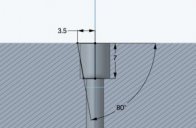
 Designing and installing heat-set threaded inserts for lower volume applications, like printing a one-off part on your Mark Two, is easy and requires only a few inexpensive tools. The best way to seat a heat-set insert is with a slightly tapered hole, as demonstrated in the following diagram. Since the insert will be installed at a high temperature, it will melt and displace a small amount of plastic from the surrounding part as it descends into the part. The small taper on the hole encourages that molten plastic to flow upwards and fully envelop the knurled outer surface of insert, while also avoiding producing a raised ridge above the surface of the part due to excess nylon having nowhere to flow.
Depending on the insert manufacturer, you may find that they will specify varying degrees of detail about the different tapers or overall dimensions for the tapered hole. Despite these variations, I’ve found that designing the actual taper in your 3D modeling program of choice is fairly easy. I generally start by modeling a hole of diameter (from the diagram above), with a depth of about 1.25x the overall length of the insert. This gives me a bit of wiggle room on the depth should any melted plastic get pushed below the threaded insert when installing it, or (depending on part orientation) if a bit of support material remains in the hole after removing supports post-printing.
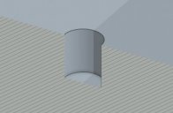
Section view of initial hole cut
If I expect the bolt or screw threading into the insert to extend further down into the part, I’ll continue the hole with a secondary smaller diameter cut, sized to allow a loose clearance fit with the desired screw diameter.
Adding a relief hole to allow a bolt to pass through the threaded insert and the part
I then add the taper with a revolved cut-type operation (the name of this might vary depending on your CAD package). The actual taper angle and length is going to depend a lot on the manufacturer’s specifications, but in this specific example I’m using an 80 degree taper.
The sketch driving the taper cut – an 80 degree taper was spec’ed for this particular insert
This process isn’t that complicated, but if you’re designing a part with a lot of threaded inserts, it can get tedious. Depending on your 3D modeling software, you may be able to use a ‘hole wizard’-type tool to add custom pre-configured countersunk holes at the desired taper with a much shorter workflow.
The final tapered hole model for a threaded insert
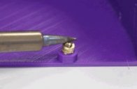
After you’ve finished designing your part and have 3D printed it, insert installation is easy. Load the insert specific installation tip into your soldering iron (this is optional – a regular soldering tip works fine, the insert installation tip just makes it a little easier to melt the insert in straight). Heat up your soldering iron, place the insert in its desired location, then press the soldering iron tip into the center of the insert, pushing down with a little force.
Once the insert exceeds the plastic melt temperature, the insert will start to descend into the part. Be careful to push the insert down straight into the hole, and not at an angle. Release the soldering iron when the insert is level with the surface of the part and let it cool before installing any screws or bolts. The threaded insert will be very hot for a few minutes after installation and skin contact should be avoided.

Share this article
Related Posts


Latest Posts


